
A Guide to Disassembling and Assembling a Computer System
A Step-by-Step Guide to Personal Computer Disassembly and Assembly
In this article, we'll learn:
The Parts of a Computer
How to Disassemble a Computer
How to Assemble a Computer
Parts of Computer System
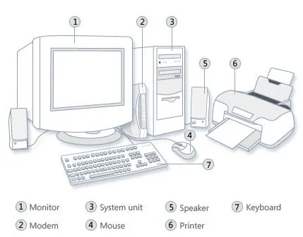
The computer system is made up of following external devices:
CPU cabinet
Monitor
Keyboard
Mouse
Printer/scanner (if attached)
How to Disassemble a Computer
Follow these seven steps carefully.
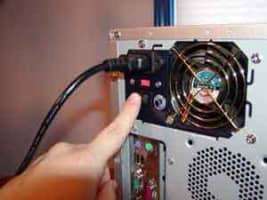
Step 1: Detach the Power Cable
The disassembling of the computer system starts with externally connected device detachment. Make sure the computer system is turned off, if not then successfully shut down the system and then start detaching the external devices from the computer system. It includes removing the power cable from electricity switchboard, then remove the cable from SMPS (switch mode power supply) from the back of the CPU Cabinet. Do not start the disassembling without detaching the power cable from the computer system. Now remove the remaining external devices like keyboard, mouse, monitor, printer or scanner from the back of CPU cabinet.
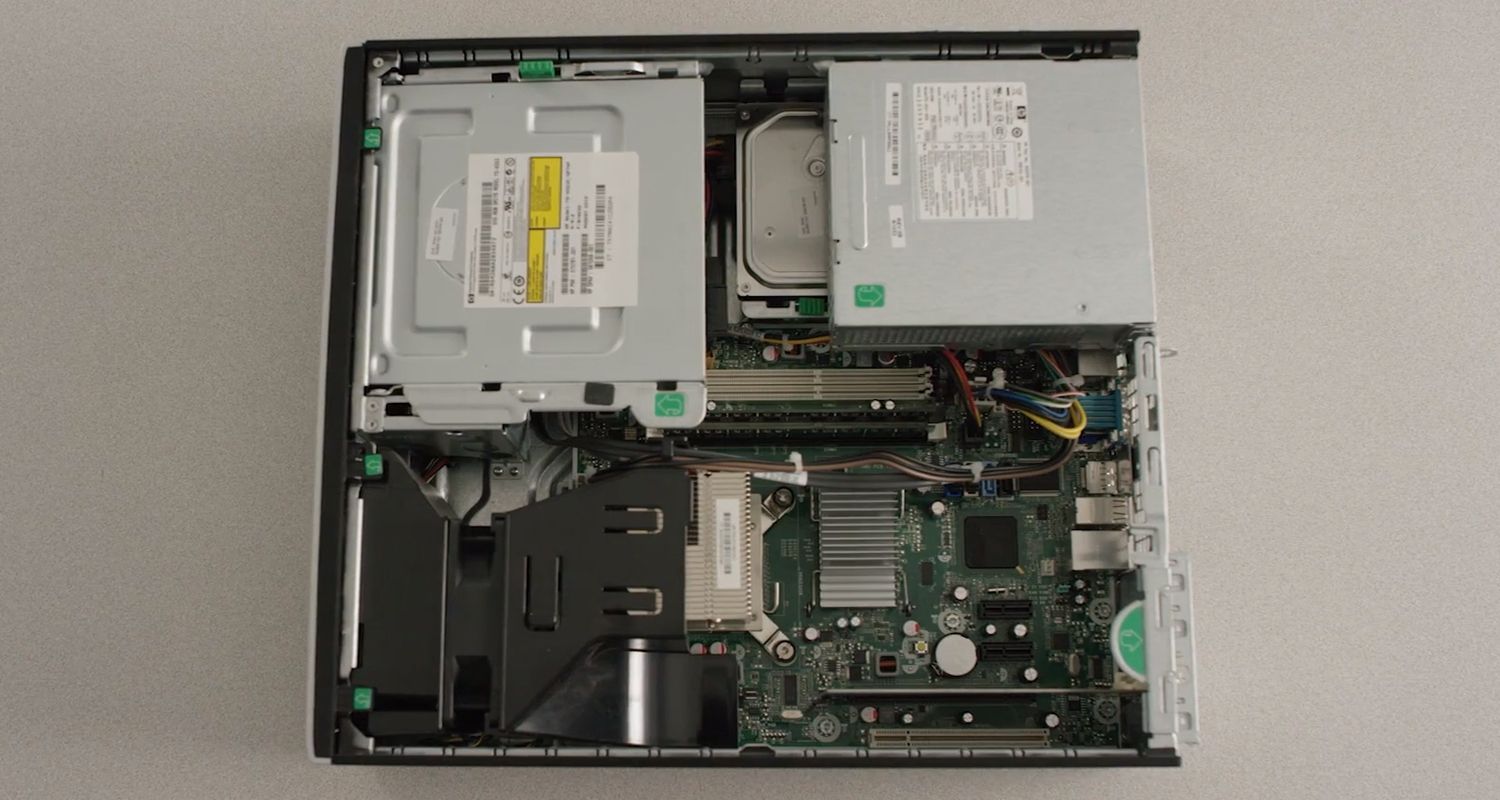
Step 2: Remove the Cover
The standard way of removing tower cases used to be to undo the screws on the back of the case, slide the cover back about an inch and lift it off. The screwdrivers as per the type of screw are required to do the task.
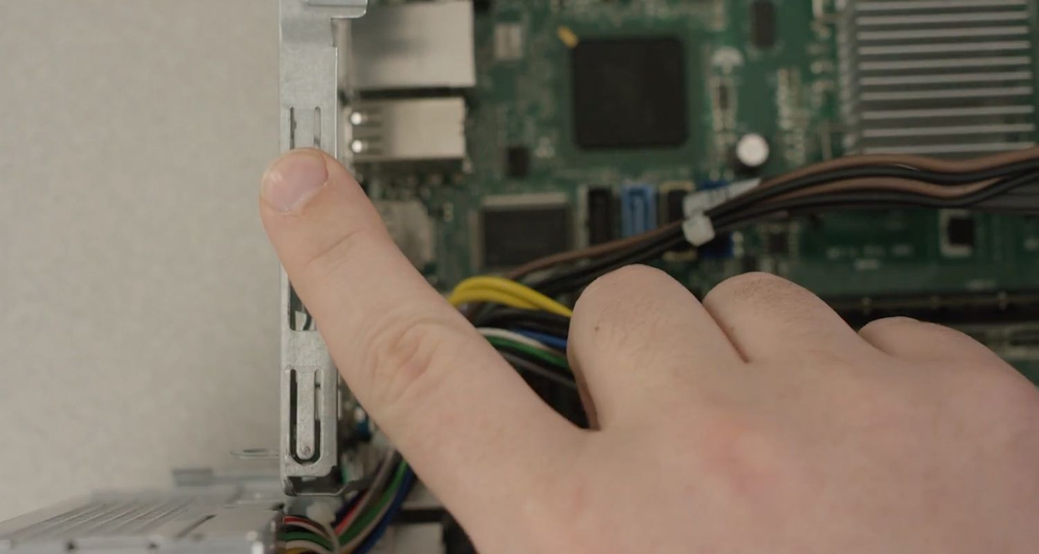
Step 3: Remove the Adapter Cards
Make sure if the card has any cables or wires that might be attached and decide if it would be easier to remove them before or after you remove the card. Remove the screw if any, that holds the card in place. Grab the card by its edges, front and back, and gently rock it lengthwise to release it.
Step 4: Remove the Drives
Removing drives is easier. There can be possibly three types of drives present in your computer system, Hard disk drive, CD/DVD/Blu-ray drives, floppy disk drives (almost absolute now a day). They usually have a power connector and a data cable attached from the device to a controller card or a connector on the motherboard. CD/DVD/Blu-ray drive may have an analog cable connected to the sound card for direct audio output.
The power may be attached using one of two connectors, a Molex connector or a Berg connector for the drive. The Molex connector may require to be wiggled slightly from side to side and apply gentle pressure outwards. The Berg connector may just pull out or it may have a small tab which has to be lifted with a screwdriver.
Now pull data cables off from the drive as well as motherboard connector. The hard disk drive and CD/DVD drives have two types of data cables. IDE and SATA cables. The IDE cables need better care while being removed as it may cause the damage to drive connector pins. Gently wiggle the cable sideways and remove it. The SATA cables can be removed easily by pressing the tab and pulling the connector straight back.
Now remove the screws and slide the drive out the back of the bay.
Step 5: Remove the Memory Module
Memory modules are mounted on the motherboard as the chips that can be damaged by manual force if applied improperly. Be careful and handle the chip only by the edges. SIMMs and DIMMs are removed in a different way:
SIMM - Gently push back the metal tabs while holding the SIMM chips in the socket. Tilt the SIMM chip away from the tabs until a 45% angle. It will now lift out of the socket. Put SIMM in a safe place.
DIMM - There are plastic tabs on the end of the DIMM sockets. Press the tabs down and away from the socket. The DIMM will lift slightly. Now grab it by the edges and place it safely. Do not let the chips get dust at all.
Step 6: Remove the Power Supply
The power supply is attached into tower cabinet at the top back end of the tower. Make sure the power connector is detached from the switchboard. Start removing the power connector connected to motherboard including CPU fan power connector, cabinet fan, the front panel of cabinet power buttons and all the remaining drives if not detached yet.
Now remove the screws of SMPS from the back of the cabinet and the SMPS can be detached from the tower cabinet.
Step 7: Remove the Motherboard
Before removing all the connectors from the motherboard, make sure you memorize the connectors for assembling the computer if required, as that may require connecting the connectors at its place. Remove the screws from the back of the motherboard and you will be able to detach it from the cabinet. Now remove the CPU fan from the motherboard. The heat sink will be visible now which can be removed by the pulling the tab upward. Finally, the processor is visible now, which can be removed by the plastic tab which can be pulled back one stretching it side way.
assembling of desktop computer
assembling of desktop computer pdf
assembling desktop computer price
assembling and disassembling of desktop computer
assembling of a core 13 desktop computer
assembling of a desktop computer
assembling a desktop computer
assembling of a computer
assembling a desktop pc
assembling of computer system
computer hardware assembly pc
assemble desktop computer india
assembled desktop computer in ahmedabad
assembling a desktop
assemble desktop computer online
assemble desktop computer output
assemble desktop computer preparation
assemble desktop computer preparation brainly
assemble desktop computer price in sri lanka
pc assembly
pc assembling
assemble desktop computer requirements


No comments:
Post a Comment